The nozzle distributor mixes the gas-liquid two-phase mixture through a small mutation hole, which makes the refrigerant gas and liquid mix evenly before entering the small distribution hole, so that the distribution is uniform. It adapts to distributors with different numbers of holes, different refrigerants and different load requirements by replacing nozzles with different small hole inner diameters.
Nozzle Distributor
Disclaimer: Product specifications may change without prior notice. To ensure accuracy, please confirm all details with our team before ordering.
Description
The nozzle distributor mixes the gas-liquid two-phase mixture through a small mutation hole, which makes the refrigerant gas and liquid mix evenly before entering the small distribution hole, so that the distribution is uniform. It adapts to distributors with different numbers of holes, different refrigerants and different load requirements by replacing nozzles with different small hole inner diameters.

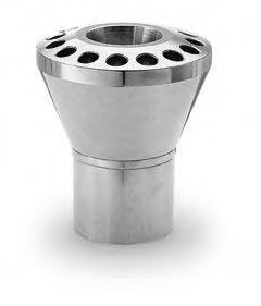
Type A nozzle distributor:

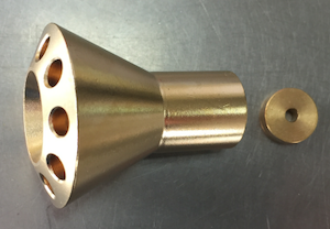
Type B nozzle distributor:

Nozzle distributor size list:
| Type | Connected capillary specification (inch) | Number of distributor holes | Nozzle specifications | A
(mm) |
B
(mm) |
C
(mm) |
D
(mm) |
E (0,
+0.015) (inch) |
F (mm) |
|---|---|---|---|---|---|---|---|---|---|
| A/B | 5/32,3/16,1/4, 5/16,3/8 | 2-32 | See attached table II | 26-120 | 16-100 | 7-38.1 | 6-15 | 5/32,3/16,1/4, 5/16,3/8 | 4-15 |
How to choose a nozzle distributor?
Step 1: Provide information to us according to the following table;
| Type | Connected capillary specification | Number of distributor holes | Nozzle specifications | A | B | C | D | E (0,
+0.015) |
F |
|---|---|---|---|---|---|---|---|---|---|
| ? (A or B) | ? | ? | Provide the model size and we’ll recommend. | we’ll recommend. | ? | we’ll recommend. | Recommended size | ||
Step 2: We provide drawings for your confirmation;
Step 3: Confirm the drawings and arrange samples.
Attached table I:
| The distributor capillary corresponds to the cooling/heating capacity of each branch | ||||||||||
|---|---|---|---|---|---|---|---|---|---|---|
| Outer diameter of distributor capillary | R-22 | R-410A | ||||||||
| 40° | 20° | 0° | -20° | -40° | 40° | 20° | 0° | -20° | -40° | |
| 5/32 | 0.26 | 0.21 | 0.16 | 0.12 | 0.09 | — | — | — | — | — |
| 3/16 | 0.53 | 0.44 | 0.33 | 0.24 | 0.2 | 0.42 | 0.31 | 0.23 | 0.18 | 0.14 |
| 1/4 | 1.1 | 0.89 | 0.67 | 0.49 | 0.39 | 1.21 | 0.9 | 0.68 | 0.52 | 0.4 |
| 5/16 | 2.2 | 1.7 | 1.3 | 0.98 | 0.79 | 2.46 | 1.83 | 1.39 | 1.06 | 0.81 |
| 3/8 | 3.7 | 2.9 | 2.2 | 1.7 | 1.4 | 4.44 | 3.32 | 2.51 | 1.91 | 1.47 |
| Branch cooling/heating capacity of refrigerant at different evaporation temperatures (unit: RT) | ||||||||||
| Applicable branch cooling/heating capacity of each branch capillary under 10PSI pressure drop | ||||||||||
Attached table II:
| Applicable cooling/heating capacity of nozzle | ||||||||||
|---|---|---|---|---|---|---|---|---|---|---|
| Distributor nozzle No. | R-22 | R-410A | ||||||||
| 40° | 20° | 0° | -20 | -40 | 40° | 20° | 0° | -20 | -40 | |
| 1/9 | 0.14 | 0.11 | 0.09 | 0.07 | 0.06 | 0.16 | 0.13 | 0.1 | 0.08 | 0.07 |
| 1/6 | 0.21 | 0.16 | 0.013 | 0.11 | 0.09 | 0.25 | 0.2 | 0.16 | 0.13 | 0.11 |
| 1/4 | 0.34 | 0.26 | 0.21 | 0.18 | 0.15 | 0.4 | 0.31 | 0.25 | 0.21 | 0.17 |
| 1/3 | 0.44 | 0.34 | 0.28 | 0.23 | 0.2 | 0.53 | 0.41 | 0.33 | 0.27 | 0.23 |
| 1/2 | 0.61 | 0.48 | 0.38 | 0.32 | 0.27 | 0.73 | 0.57 | 0.46 | 0.37 | 0.31 |
| 3/4 | 0.92 | 0.72 | 0.58 | 0.48 | 0.41 | 1.1 | 0.86 | 0.69 | 0.57 | 0.47 |
| 1 | 1.23 | 0.96 | 0.78 | 0.64 | 0.55 | 1.47 | 1.15 | 0.92 | 0.76 | 0.64 |
| 1-1/2 | 1.79 | 1.4 | 1.13 | 0.94 | 0.8 | 2.14 | 1.67 | 1.34 | 1.1 | 0.92 |
| 2 | 2.46 | 1.92 | 1.55 | 1.29 | 1.1 | 2.93 | 2.3 | 1.84 | 1.51 | 1.27 |
| 2-1/2 | 1.07 | 2.39 | 1.93 | 1.6 | 1.37 | 3.66 | 2.86 | 2.3 | 1.88 | 1.58 |
| 3 | 3.68 | 2.87 | 2.32 | 1.93 | 1.65 | 4.39 | 3.44 | 2.76 | 2.26 | 1.9 |
| 4 | 4.92 | 3.84 | 3.1 | 2.58 | 2.2 | 5.88 | 4.6 | 3.69 | 3.02 | 2.54 |
| 5 | 6.07 | 4.74 | 3.83 | 3.18 | 2.72 | 7.25 | 5.67 | 4.55 | 3.73 | 3.13 |
| 6 | 7.28 | 5.68 | 4.59 | 3.81 | 3.26 | 8.69 | 6.8 | 5.45 | 4.47 | 3.76 |
| 8 | 8.77 | 6.84 | 5.52 | 4.59 | 3.93 | 10.5 | 8.19 | 6.57 | 5.39 | 4.53 |
| 10 | 9.83 | 7.67 | 6.19 | 5.15 | 4.4 | 11.7 | 9.18 | 7.36 | 6.04 | 5.07 |
| 12 | 12.1 | 9.47 | 7.65 | 6.36 | 5.43 | 14.5 | 11.3 | 9.09 | 7.46 | 6.26 |
| 15 | 15.1 | 11.7 | 9.48 | 7.88 | 6.74 | 18 | 14.1 | 11.3 | 9.25 | 7.77 |
| 17 | 16.8 | 13.1 | 10.6 | 8.81 | 7.54 | 20.1 | 15.7 | 12.6 | 10.3 | 8.69 |
| 20 | 20.3 | 15.8 | 12.8 | 10.6 | 9.08 | 24.2 | 19 | 15.2 | 12.5 | 10.5 |
| The number of the nozzle represents the capacity. For example, the number 1 indicates the nozzle for air conditioners with a cooling capacity of 1HP. The nozzle corresponds to the cooling/heating capacity (unit: RT) at different evaporation temperatures. | ||||||||||
| Temperatures are in Fahrenheit | ||||||||||
Note: When selecting the capillary outer diameter and nozzle corresponding to the capacity listed in the attached table I and attached table II, the capacity can be changed within 0.5-2 times.
You must be logged in to post a review.
⚠️Disclaimer: Product specifications may change without prior notice. To ensure accuracy, please confirm all details with our team before ordering.


Reviews
There are no reviews yet.